Pipe Stress Analysis


Software and Code Compliance
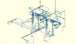
NeuMech Solutions provides pipe stress analysis services Using Autopipe and Caesar II. The services cover process and powered piping systems according to ASME B31.3 and ASME B31.1 codes. Compliance to other piping codes can be performed as well.
Load Cases
To obtain reliable results, we work on all details to ensure the stress model is identical to designed piping system and all the potential thermal scenarios are captured. Load cases are defined as per thermal scenarios and the most critical pressure and temperature combinations, as well as occasional and dynamic loads as applicable.
Analysis Procedure
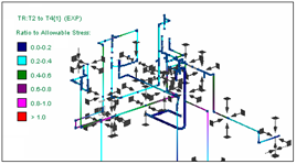
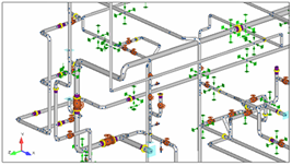
Neumech solutions provides a comprehensive piping stress analysis that covers all essential components. Code stresses are checked to ensure code compliance. Equipment nozzle loads are checked for operating load case and for all the load sensitive equipment connected to piping systems. For high pressure systems flange check is done. Occasional loads such as wind and seismic are applied as per geographical characteristics of the plant. The impact of safety relief valve and the impact of their dynamic load on the piping system are checked, as well as other types of dynamic loads that are applicable. As a result of the comprehensive stress analysis, piping supports including their type and location are provided. Also if the piping system requires any modifications to be able to accommodate the stresses, the piping re-design is done by Neumech Solution and the updates are provided in a format compatible with client’s piping design software.
Stress Analysis Report
After completion of pipe stress analysis two documents are prepared as the report. First document is the pipe stress analysis report that includes the program and piping code used, load cases, design conditions, code stresses results, nozzle loads, and other types of results. This document provides an overall view of the piping system stresses, forces, and displacements under the applied pressure, temperature, and external loads for each load case. The second document is pipe support report that provides forces, moments, and displacements for each support. Piping supports locations can be prepared both as a marked up on piping fabrication drawings or as a 3d file to be added to piping model, as per client’s preference.